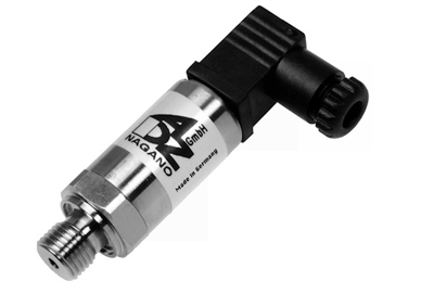

เซนเซอร์แปลงความดัน Pressure Transmitter
รุ่น SHP
คุณลักษณะ
This SHP has been designed for challenging tasks of measuring and control. It has a total error of typically 0.1% (max. 0.15%) under RT referential conditions. By means of a contact controlled by a solenoid, the zero point of a transmitter allows for subsequent adjustment in order to correct errors caused by drift or the installation position, for example. With the SHP-P version, various parameters of the transmitter can be altered by means of a handheld device or the PC. Apart from scaling the measuring range at a ratio of 4:1, it can also be shifted, which permits a transmitter of a nominal range of 0 to 10 bar to be set at a measuring range of 1 to 4 bar. Also the measuring rate and type of output filter, the characteristic curve (inverting, taking the root, or as a free characteristic curve on 11 nodes) and, in a wide range, the output signal can be adjusted. Its robust design guarantees a high level of reliability and safety, also in rugged conditions. Its stainless steel diaphragm is fully vacuum-tight, extremely burst-resistant and applicable with all standard media in hydraulics, pneumatics, etc., as long as they are compatible with stainless steel.
- Scalable measuring ranges from 0…10 mbar to 0…2000 bar
- Output signals 4…20 mA, 0…10 V, 0…5 V, digital and others
- Resetting and new zero adjustment
- Precision 0.15 % (optional 0.1 %)
| PRESSURE RANGE | |||||||||||
|---|---|---|---|---|---|---|---|---|---|---|---|
| SILICON TECHLOGY | |||||||||||
| Measuring tange* | p [mbar] | 10 | 16 | 20 | 25 | 40 | 60 | 100 | 250 | 600 | 1000 |
| - Overload pressure | p [mbar] | 300 | 300 | 300 | 300 | 300 | 300 | 300 | 300 | 300 | 300 |
| - Burst pressure | p [mbar] | 500 | 500 | 500 | 500 | 500 | 500 | 500 | 500 | 500 | 500 |
| Stainlrdd steel diaohragm | |||||||||||
| Measuring range* | p [bar] | 1,6 | 2,0 | 2,5 | 4,0 | 6,0 | 10,0 | 16,0 | |||
| - Overload pressure | p [bar] | 6 | 6 | 6 | 10 | 20 | 20 | 40 | |||
| - Burst pressure | p [bar] | 9 | 9 | 9 | 15 | 30 | 30 | 60 | |||
| Measuring range* | p [bar] | 20 | 25 | 40 | 60 | 100 | 160 | 200 | |||
| - Overload pressure | p [bar] | 40 | 100 | 100 | 200 | 200 | 400 | 400 | |||
| - Burst pressure | p [bar] | 60 | 150 | 150 | 300 | 300 | 600 | 600 | |||
| Measuring range* | p [bar] | 250 | 400 | 600 | 1000 | 1600 | 2000 | ||||
| - Overload pressure | p [bar] | 750 | 750 | 840 | 1200 | 2400 | 2400 | (vacuum, relative pressure,+- or absolute pressure are available) |
|||
| - Burst pressure | p [bar] | 1000 | 1000 | 1050 | 1500 | 3000 | 3000 | ||||
| ELECTRIC PARAMETER | |||||||
|---|---|---|---|---|---|---|---|
| signal | US [VDC] | RL [kΩ] | RA [Ω] | ||||
| Output signal* and | RA in Ω | 4...20Ma | (2-wire, 3-wire) | 9...32 | acc. to RA≤ (US-10V)/0,02A | ||
| Maximum acceptable burden | RA | 0...10 VDC | (3-wire) | 12...32 | >5,0 | ||
| Response time*(10-90%) | t [ms] | 4 | 10...4000 | ||||
| Withstand voltage | U [VDC] | 33 | |||||
| EMC characteristics | EN61000-4-2 | level 3&4 | |||||
| EN61000-4-4 | level 4 | ||||||
| EN61000-4-5 | level 3 | ||||||
| EN61000-4-6 | level 3 | ||||||
| EN61000-4-16 | level 3 | ||||||
| ACCURACY | |||||
|---|---|---|---|---|---|
| ACCURACY @RT | % of the range | ≤ 0,15** | option ≤ 0,1 | 99 icnl. nonlinearity, hysteresis, repeatability, zero-offset- and final-offset (acc. to IEC 61298-2) |
|
| BFSL | ≤ 0,05 | ||||
| Non-linearity | % of the range | ≤ 0,05 | |||
| Repeatability | % of the range | ≤ 0,00 | |||
| Stability/year | % of the range | ≤ 0,10 | |||
| ACCEPTABLE TEMPERATURE RANGE | |||
|---|---|---|---|
| Measuring medium | T [°C] | -20...85 | |
| Ambience | T [°C] | -20...85 | |
| Storage | T [°C] | -40...105 | |
| Compensated range* | T [°C] | -10...80 | |
| Total error | % of the range | -40°C 0,50% | |
| % of the range | 85°C 0,50% | ||
| MECHANICAL PARAMETER | |||||
|---|---|---|---|---|---|
| Parts in contact with the measuring medium* | stainless steel, silicon | ||||
| Housing* | stainless steel | ||||
| Shock resistance | g | 1000 | acc. to IEC 68-2-32 | ||
| Vibration resistance | g | ~120 | (depending on design) | ||
| CE-conformity | EC Directive 89/336/EWG | ||||
| IP system of protection | THE IP system of protection as specified in the data sheets generally applies, with their mating plud connected. Relative pressure transmitters usually require a centilated mating plug and/or cable to aloow for pressure comsation. From a pressure range of 60bar, a ventilated mating plug and/or cable is not necessarily required. | ||||
| * others upon request | |||||


